Certain Aircraft just need to be modeled a certain way, if you are a fan. The F-14 has many fans…
KAZAN’s SPINE SET KAZ005HAS is designed for the Hasegawa kits in 1:48th scale, although technically superior kits have been released and will apparently continue to be. Nevertheless, the Hasegawa line of kits are still very viable and any Tomcat fan has at least one in the house somewhere. At the time that this set began to be conceptualized, there were only the Hasegawa, Monogram and Academy kits around and the Hasegawa kit was the best of the bunch. It was good then and it’s still good now. The Tamiya kit is really designed for guys who don’t want everything hanging down and off it, and it’s not a cheap kit.
Prep Work
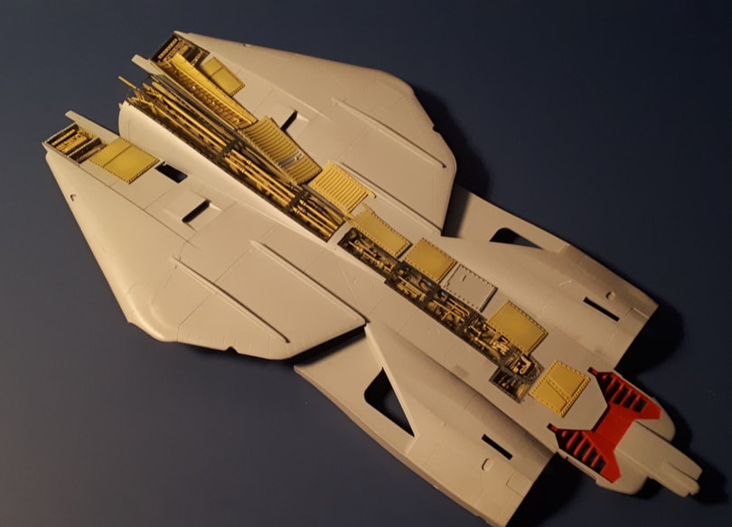
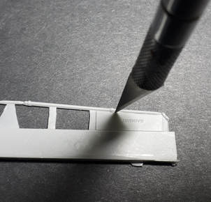
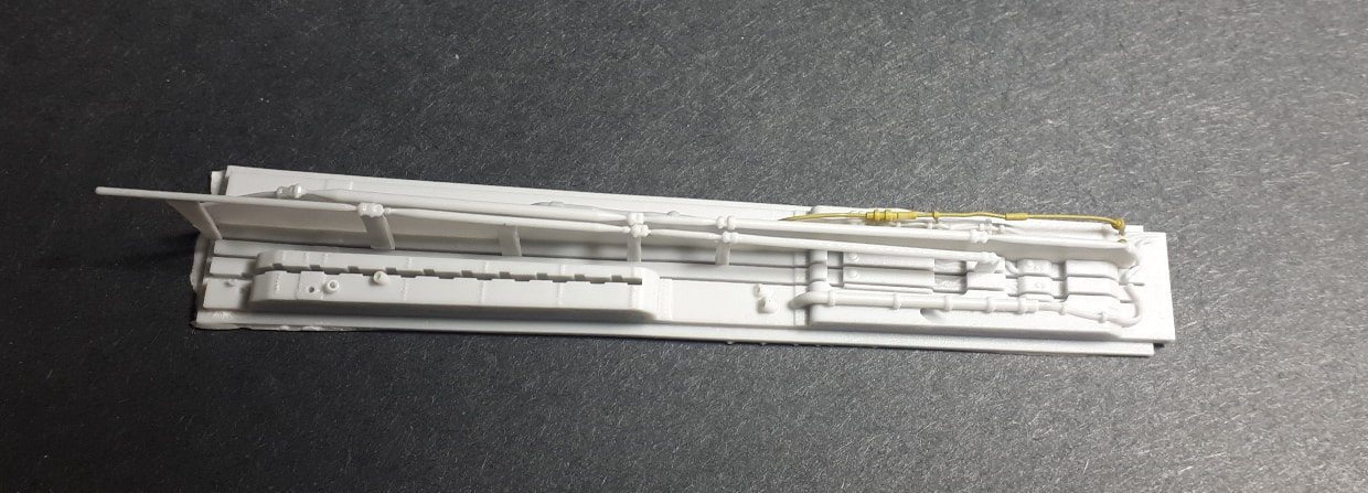
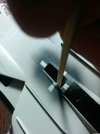
The detail set project depicted here starts with the opening up of the panels along the spine and at the upper front end of the intakes. It’s a pretty easy step and generally speaking, you follow the existing panel lines to remove the panels. The only exception is the smaller panel immediately aft of the stiffeners. This panel really has a pronounced trapezoidal shape to it, and it should be a little more rectangular. This is explained in the instructions, as is the procedure to cut out the correct shape, using the photo-etched piece as a guide. Annoying, perhaps, but simple.
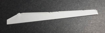
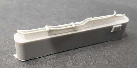
This is basically a front half/back half assembly, and the two main spine floor sections are designed to mate together as shown. Note the tongue of the front part that fits into the groove of the rear part. Casting being what it is, you may need to clean up the groove of the rear part if there is any residual resin on it that prevents a good joint. Any parts that had residual resin on it preventing the two parts from mating properly are rejected during packing. You should have no issues here.
|
|
Plumbing and Conduits
|
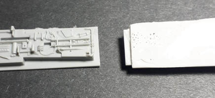
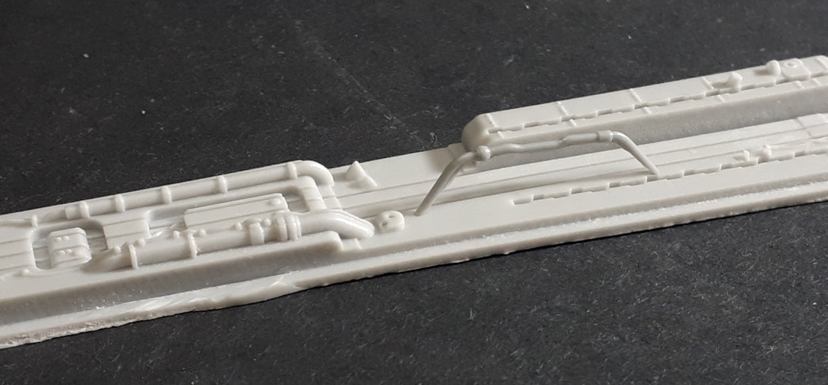
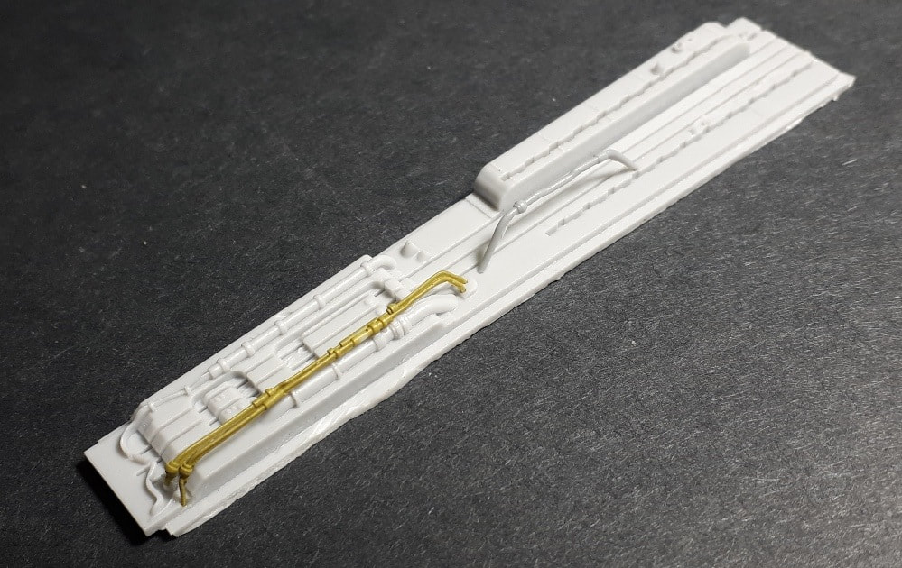
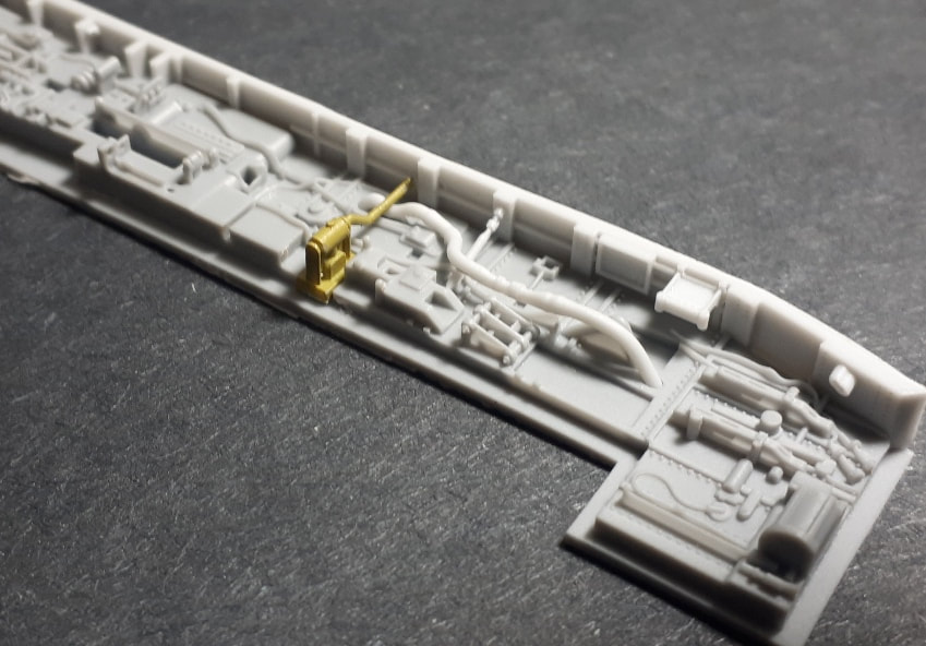
Step Two of the instructions installs the plumbing into the forward half of the spine. There are five main plumbing and conduit parts (plus four outside linkage parts, two of which are used) to be placed and these are cast with a thin carrier film from which the actual part needs to be removed.
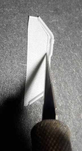
The removal of the parts from the carrier is not difficult, but if you’ve had more coffee than you’re used to, or maybe not enough, you just need to be a bit more careful and patient here. The key is to use a fresh knife blade and always cut away from the actual part to be used and away from corners. This is intuitive once you get going. You will notice that the resin we use actually facilitates this nicely. It’s not brittle and has a lot of tensile strength. Really…just take your time and use new knife blades. No, we don’t own stock in X-Acto or ARM. We mean it. Prep parts 14 and 15 last. They are the thinnest and doing the other parts first will let you get a feel for this step. By the way…use a new knife blade, if we neglected to mention it. |
|
|
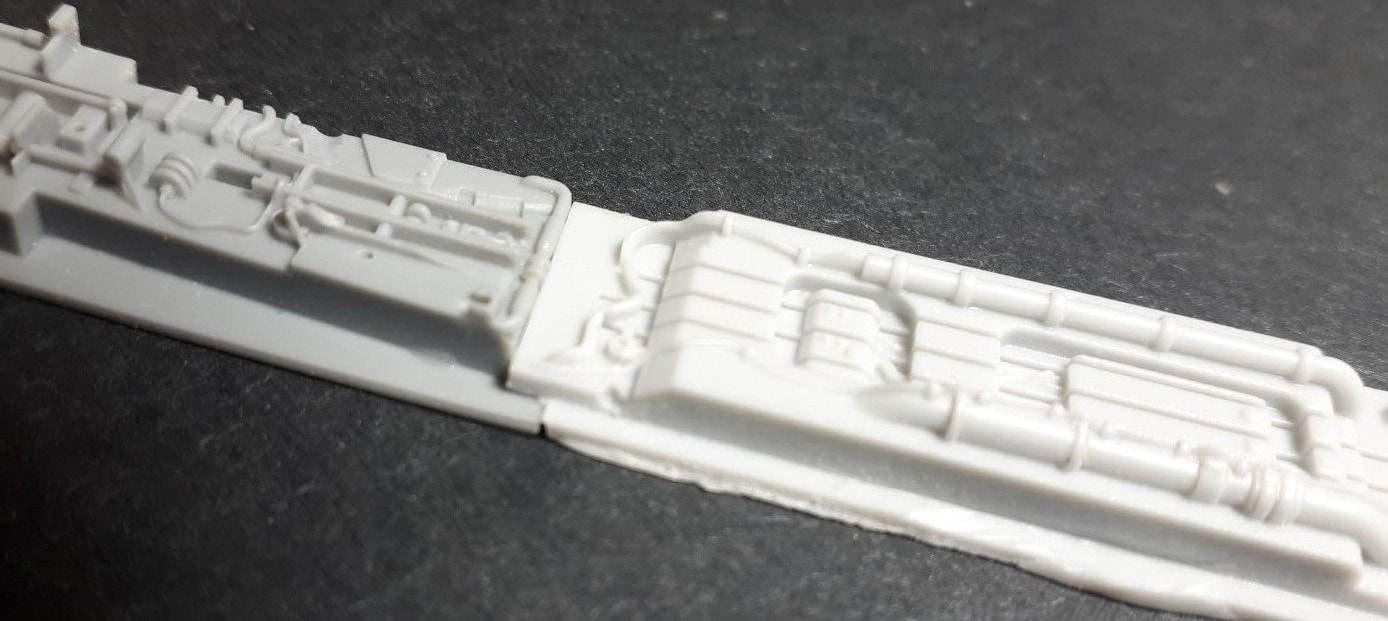
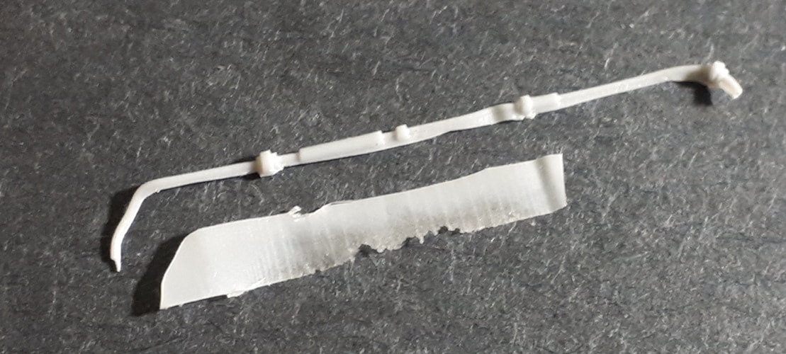
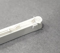
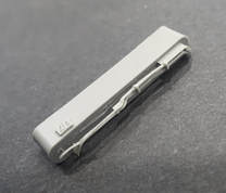
These shots illustrate the removal of the carrier from Part 1 and the same part’s final resting spot.
|
|
|
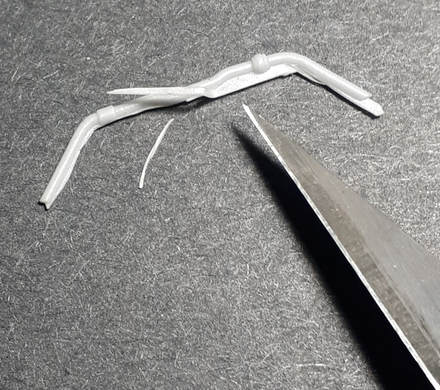
These are Parts 14 and 15. Don’t pay any attention to the colouring of the parts here. This is not a painting guide, and the parts were painted to aid visibility for the purposes of this tutorial.
|
|
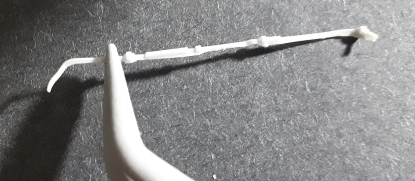
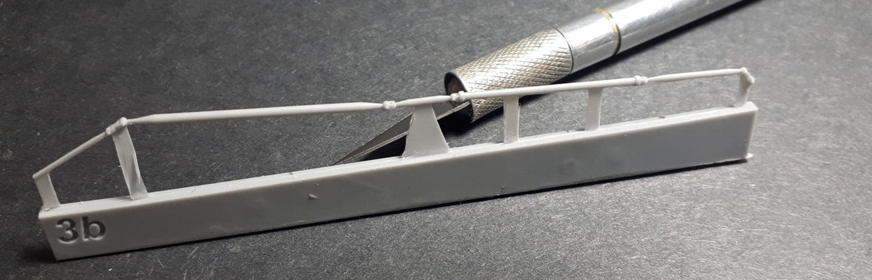
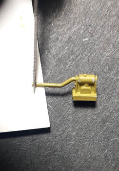
The Linkage Rods (Parts 3 and 10)
|
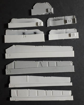
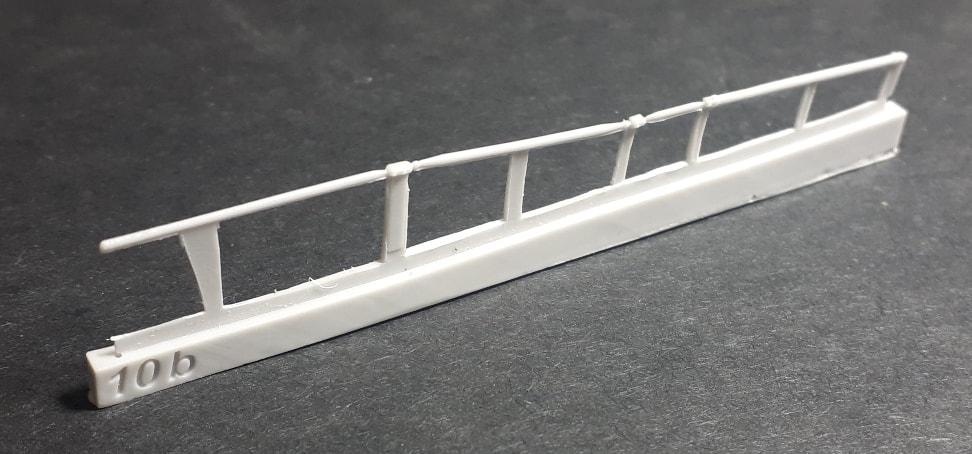
There are three linkage rods that run down the front half of the spine with the centre one continuing on down through the rear half. Designing these in resin to be ‘doable’ wasn’t easy, but the outcome is certainly convincing and looks great. Initially, the assembly of this whole set requires the two outer rods of the front half, leaving the third (middle) rod off for now. Why? You’ll see later. It has to do with the way it links up with its rear half counterpart. These outer linkages are 3a and 3b. ‘a’ and ‘b’ are an option - you pick one or the other. 3a is simpler and you just sever the part WITH its carrier film at the base where it attaches to the casting block. The carrier film inserts into the two long outside grooves in the spine floor. Part 3b is treated in a similar way, but eliminates much of the carrier and gives a little more of a suspended look. You’ll note the blocks in the carrier section of the casting that say ‘remove’ on them. Remove them. Their edges serve as knife guides, and again…use new knife blades and cut away from the actual part and away from corners. In tight corners, use the knife vertically and gently use an up and down piercing motion, progressing along the corner to form a cut. The outer front half linkage rods Parts 3 (either a or b) fit such that the very back of their supports sit at the very back of the grooves of the spine floor. This will place them in their proper alignment. Dummy up! This is important – this will be used to align the centre front linkage rod in its correct position. The good thing about this setup is that the bottoms of the rods, and even the cables and conduits before, are cast in a way that the bottoms of these parts don’t need the carrier film trimmed all the way to the part, since it will be invisible from the angle from which it will be viewed. It’s like horseshoes and hand grenades (and nukes, I suppose)….close enough is good enough. The centre linkage rod (Part 10a or 10b, plus 10c) runs down most of the length of the spine and comes in two parts, front and rear. The front half has a similar option attached to it that the Part 3 do and is done the same way. You choose either 10a or 10b. Part 10c is only one and it’s the rear half linkage rod, and you’ll note that it slightly skews from the centerline towards the rear. Your parts not warped. My Part 10b ended up being a bit thick at the bottom and needed to be sanded down a bit. When I cut it away from its casting block and removed the thicker sections marked ‘REMOVE’, I created a bit of a lip around the part, causing fit issues with the corresponding groove. You do need to be a bit careful with this, if you need to do this as well. The best thing to do is to maybe tape the part down on a hard surface and then tape the individual support legs down, too, than run your sanding stick over the bottom sections of each leg. Turn part over and repeat. I ended up not doing this and broke off one of the legs, but no big deal. It’s not essential. Now, bear in mind that this is a dry-fit with one outer linkage (Part 3b) and the centre rod (Part 10b). Part 10b suffered a bit of warping during the sanding stage, but this gets straightened out when it is set in the centre groove. What’s important to note here is that the outer linkage is set to the very rear of its groove as would be its opposite. Then, the centre linkage is placed in relation, but note where the front support leg sits in the spine floor and that the two sets of joints that are basically in line with each other. That’s the spatial relationship between these front linkages. Also, do not glue the centerline linkage rod in place (Part 10a or b) at this stage. It still needs to be in the right place in relation to the rear half linkage, Part 10c. The integration of the front and rear halves comes towards the end of assembly, and that will be the time for gluing the centre links in place. |
|
The Rest of the Front Half…
The remainder of the parts are simply glued in place as per the instructions. No big suggestions there.
When this was all being designed, the holes in the spine floors that accept the ends of their corresponding ductwork were oversized by a bit to allow them to fit. It may still be necessary, in some cases, to drill out the openings a little with a small (no.80 or 81) drill bit. In the case of this assembly, somewhere around sixty kits into production, it wasn’t. However, a light sanding of the ends of the cables and conduits was always part of the process. There, the carrier film does need to go. But again, the resin itself lends itself well to this type of work, because it’s not brittle. Just be patient.
Parts 4 and 5 are these tiny little wires and really, these are tough to remove from their carrier because of their diameter, which is not much larger than the film. It’s easier to just use these as a template to fashion some brass or copper wiring of 0.2mm diameter and use that instead.
The Rear Half
|
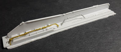
The rear half assembly is a fairly straight forward affair. It seems to be a good idea to begin with Part 9, a conduit that fits snug against the bottom of the rear half floor. The thing to watch for is that it really needs to be snug against the floor, which is how it is designed to sit, but if you are careless of this fact, it will hamper the fit of Part 6. It also needs to allow the brace in the sidewall to fit over top of it. As an exception to the rule, try and clean the carrier film of Part 9 right to the part itself to facilitate that fit. It doesn’t need to be pretty – it will not be visible, but it does need to not hamper the fit of Part 6. Again, a gentle sanding stick run around the ends will assure a good fit.
The carrier film on Part 6 is best removed with the part on its casting block, because it gives you something to hold on to as you remove it. Part 6’s end had to be snipped by a gnat’s hair to let it sit far enough into the floor where it won’t obstruct the fit of the left sidewall. Note also that the carrier under the brace bar in the sidewall (Part 18) needs removal. It’s delicate, but care and a new knife blade will lead to good things. Use more light strokes with the knife rather than less but heavier ones. See how that conduit (Part 9) flows above the brace bar coming down from the sidewall and below the transverse bar of Part 6. Part 23 threads through the photo-etched part PE9. You can install the PE part first and then thread the resin piece Part 23 through it, then rotate it so that its peg sits in the square hole that accepts it. The pin end of this part attached to the linkage system that is Part 19, which itself sits on a couple of pedestals. |
|
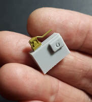
That Part 17…
|
Part 17 is an interestingly cast, two-line part that comes off the casting block as a single piece. The issue with this was that the two lines are connected in a bracket type assembly and it was deemed most practical to cast as a single unit. The carrier films are best removed a little at a time as you progress through to the finished product. Again…no need to be meticulously clean on the bottom of the part, where the film was attached to the part. You won’t see it.
|
|
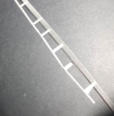
The Photo-Etching
|
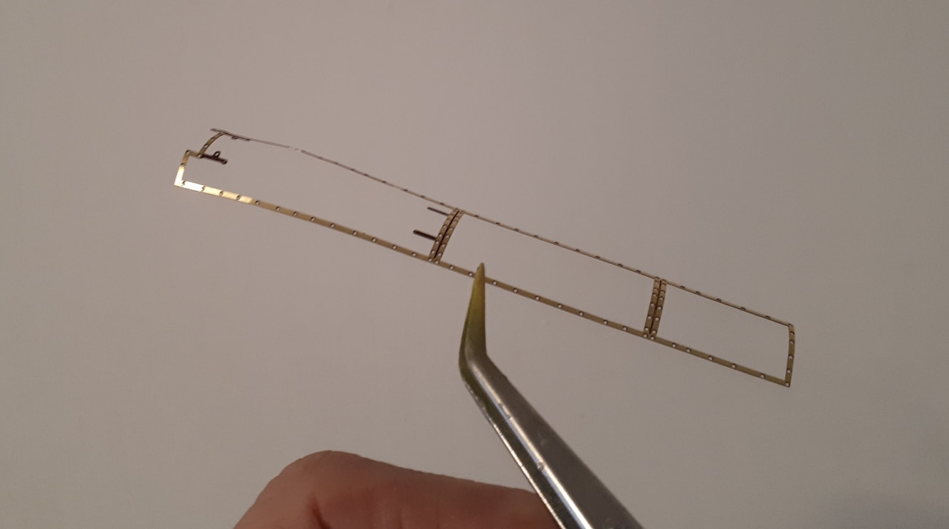
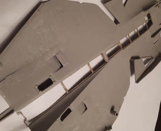
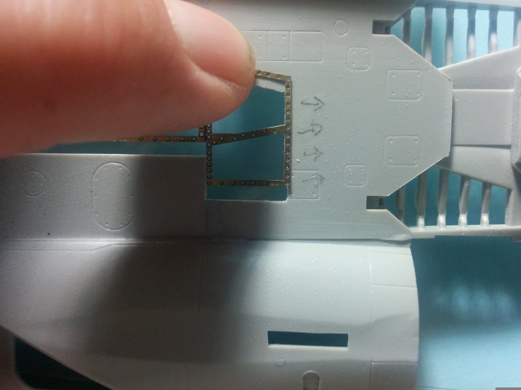
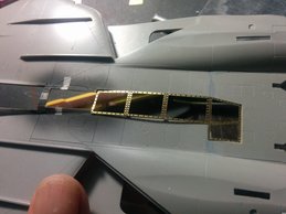
It is very important to take the necessary time and apply the necessary patience in removing the panels along the spine. As mentioned earlier, the panel lines are generally followed, except for that panel behind the stiffeners. Cutting the panels out should yield a nice, clean edge and to make the placement of the brass framework easier, it’s a good idea to sand the edges in such a way as to provide a bevelled border. This means that if you look at the opening from the inside of the fuselage (you have the fuselage turned over) the opening will be a tad larger than if you are looking at the outside fuselage (the surface that will be visible). What this will do is allow you to place the photo-etched frames a lot easier from the inside of the fuselage. Gluing should always be done from the inside, too. Obviously, this is to keep from glue build-up from being visible on the outside, where you don’t want it.
The placement of the frames in the rear half is pretty straightforward. No compound curves here. It is important, though, to gradually sand outward, making the panel bigger, and dry-fitting the component until you get the fit you need. The front half is a bit trickier, mostly because it’s bigger, has a three dimensional shape to it, and is fragile. Start by taking the piece (PE1) and putting it face down on a stack of newspapers. Role something like the handle of your knife across it laterally to give it an initial curvature that roughly mimics the shape of the spine. This will make it easier to attain a final shape as you near completion. Start at the back end by inserting the frame there from the inside of the fuselage. Here, the idea of that bevelled edge becomes apparent. Also, a really good product to use in these types of cases is Microscale’s Liquitape. Actually, if you tend to use photo-etching at all, this should be part of your toolkit. It’s great stuff and you can use it to help you hold the part in place while you glue it down. So, start at the back end and continue on forwards until you get to the front, about an inch at a time or so. As you adhere the very forward ends of the frame PE1 into the fuselage, you’ll find that it will acquire the curvature that it needs to have. One note of warning, though…this part tends to be susceptible to damage until the top and bottom fuselages are glued together, providing some much needed stability. Attaching the Front and Rear Spine Assemblies in Place. These, as indicated in the instructions, are only taped together, and the centre front and rear linkages are not attached to one another, either. Place the taped assemblies as one unit into the top fuselage, turned over. The fit of the sidewalls of the bays is not really important, and you may have some gaps that are completely invisible in the end product. Once you are happy with the positioning, add some CA glue in spots. Once there is enough CA to hold the parts in place, and you are happy with the location, reinforce the length of the joint with an epoxy type glue. The ‘five minute’ stuff works well. If you plan on using the wing box set in conjunction with this spine set, you will want to reinforce the joint further with some epoxy putty. This will help secure the spine assemblies in place while you also remove the panels for that set. It would really bum you out if that fell out on you during that process! |

|
DROP US A LINE
Let us know what you'd like to see (email is preferred please). Maybe we're interested?
|
|
phone |
address |
22 Murrayhill Court
Kitchener, Ontario Canada N2E 1N9 |